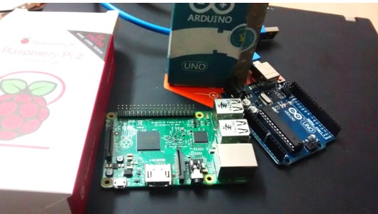
Step 2 – Connect Raspberry Pi to Arduino and able to establish the same configuration which was achieved via computer and Arduino
Since there are many sub-steps, we will cover this step in this part 3 and the the following part 4 of this series.
Here, we are going to do the Raspberry Pi configuration and connecting it to the Arduino Uno.
Raspberry Pi is capable of running a complete operating system and the real advantage is the capability to running with so less power consumption and the easiness to interface with other micro-controller and digital/analog devices .
Why do we use Arduino here ?
Raspberry Pi is a fine little computer board, though not nearly as good as the Arduino when it comes to I/O capabilities.
Since our experiment has a sensor network setup, it will be simpler to interface it with Arduino Uno.
Once we have the Arduino connection setup , then we can connect the Raspberry Pi through serial connection and do wonders with it.
Now, we are going to see how you can setup the connection of Raspberry and Arduino Uno in 10 simple steps:
Step 2: Write the image to the disc (SD card) using Win32 image. Bear in mind that If you copy and paste the disk to image then it will not work.
Step 3.Open the SD card in your computer and add following line to the end of file cmdline.txt. Make sure that you leave a line break at the end, as in Linux it will be assumed to be execution of the command. It will be better to use notepad++ to edit, as sometimes notepad can insert some windows specific characters in the file which will not work in Linux (Raspberry system).
In the above image , the Raspberry IP address is first one and our Ethernet port IP is second one. This will enable to connect Raspberry Pi to the Internet through our computer.
Step 4: Change the IP of your Ethernet port to the IP which you have specified in the config file. In this tutorial, it is 192.168.137.1
Step 5: Install Xming and Putty. Putty will be used to establish a SSH connection to Taspberry Pi and Xming will be used to create a graphical session .Download link of Putty and Xming.
Step 6: Once you have installed them, run Xming server and then open Putty.
.
Enter the IP address of the Raspberry Pi you configured in step 3 i.e :192.168.137.10
Also make sure that you have SSH enabled in X11 :
Now press open.
Step 7: It will ask for user name and password: username is pi and password is raspberry
Now you are inside the Raspberry Pi 🙂
To view the graphical interface, you have to type lxsession and if everything is correct you will be able to see the graphical navigation window of Raspberry:
Step 8: After you have closed the graphical session using CTR+ Z, install Arduino to Raspberry, using the bellow commands:
sudo apt-get update
sudo apt-get install Arduino
After the installation, you will get a success message as well.
Step 9: Open the graphical session again using lxsession command and open the Arduino sketch IDE that has been installed:
Step 10: Now we have the Arduno’s sketch installed in the Raspberry Pi OS. This final step is to check if we can see the serial port connection visible (/dev/ttyACM0 in Raspberry OS).
We will use this port for our devices’ communication, in the use cases.
In part 4 we will install Java in order to enable a Java program to communicate with Arduino’s serial port 🙂
If you have not seen yet, double check the introduction and the first part of this SAP HANA IoT series. Today, in this article we are going to perform:
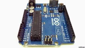
Step 1 – Connect our Arduino to a Computer and checking if the analog input is working perfectly
For this experiment we have photo sensors that will detect the light intensity and give the data to a computer by serial port communication.
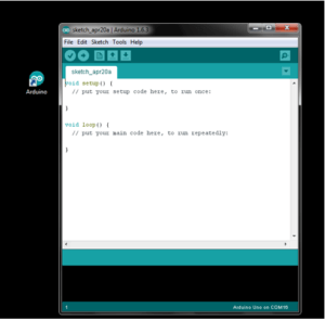
First, install the Arduino Kit from here, to your computer. In our scenario, we will be using Windows.
It looks like this after the installation:
Check also the serial port which is connected to Arduino and set the right port in your installed software:
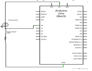
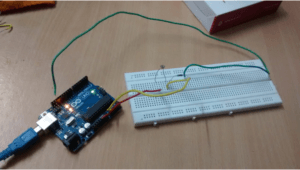
Now, for this demo we are going to follow the circuit diagram below:
Our circuit looks like this:
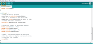
Let’s have a look at the code which takes analog input from serial output:
/*

Analog input, analog output, serial output
Reads an analog input pin, maps the result to a range from 0 to 255
and uses the result to set the pulsewidth modulation (PWM) of an output pin.
Also prints the results to the serial monitor.
The circuit:
* potentiometer connected to analog pin 0.
Center pin of the potentiometer goes to the analog pin.
side pins of the potentiometer go to +5V and ground
* LED connected from digital pin 9 to ground
created 29 Dec. 2008
modified 9 Apr 2012
by Tom Igoe
This example code is in the public domain.
*/
// These constants won’t change. They’re used to give names
// to the pins used:
const int analogInPin = A0; // Analog input pin that the potentiometer is attached to
const int analogOutPin = 9; // Analog output pin that the LED is attached to
int sensorValue = 0; // value read from the pot
int outputValue = 0; // value output to the PWM (analog out)
void setup() {
// initialize serial communications at 9600 bps:
Serial.begin(9600);
}
void loop() {
// read the analog in value:
sensorValue = analogRead(analogInPin);
// map it to the range of the analog out:
outputValue = map(sensorValue, 0, 1023, 0, 255);
// change the analog out value:
analogWrite(analogOutPin, outputValue);
// print the results to the serial monitor:
Serial.println(sensorValue);
// wait 5 milliseconds before the next loop
// for the analog-to-digital converter to settle
// after the last reading:
delay(500);
}
Here we are trying to read the analog signal from the photo sensor, via Arduino, and then Arduino will send it via serial port to the computer and use it to show the data sensor reading.
After writing the program you should upload the program to the Arduino Uno.
And now to see the magic happening, open the serial monitor in top right side of the program.
In the first part of this article we discussed what UX means, what a Persona is and described the UX first design phase.
In this second phase, you have to map your critical ideas, customer profile and customer requirements into technical components.
It is the Wire Framing phase.
What is Wire Framing ?
Wire Framing is when your ideas and all of your design that are in your mind, which you got by talking with your customer in the workshops, will be drawn into sketches that will look like real solutions, like web applications or mobile apps.
There are some useful tools for Wire Framing, in the market.
What are the main Wire Framing tools ?
Moqups and Balsamiq
Moqups and Balsamiq are framing tools, you can use for free during the evaluation period.
They are very simple to use and with Moqups is even easy to share through Google Drive. You can give the link to your customers and let them share and find out if they really like the user interface of the final design.
We will be writing reviews of these tools in future articles.
SAP Protyping Toolkit
On the SAP side, you have the prototyping toolkit in SAP Experience, where you can download it.
Prototyping toolkit is not a tool, it’s a PowerPoint and it’s a smart approach by SAP to give a wire-framing solution.
In there you can find slides with sample applications, which is nothing but the components that you will change to show to your customers.
Go for SAP Experience and checkout. There are many small details that SAP has covered.
It is a wireframing tool that automically generates code and can be useful for designing very simple mobile applications. It is built in Node.js.
Topics to keep in mind during Wire Framing phase
Try to design the solution along with your Client since immediate feedback and many interactions will save time.
It is very important to get a fast feedback from the Customer regarding his requirements.and he should understand what they are going to get after this solution is being delivered.
SAPUI5 technology and Fiori are so much new that only a few customers have experience with this kind of user interface.
This iterative and incremental process will save you time and effort because you will have an idea of the development effort.
Bear in mind there can be situations where you can have the exactly same designs but the effort required are considerably different for each one. The UI is equal but the UX is much different.
If you don’t have any idea about the effort of the development then it will be difficult to choose the right design. For this reason every UX designer should have some idea about the development effort. It always helps.
In this article, we are going to talk about User eXperience a little more.
What is UX ?
Traditionally people are confused with what is user experience and what is the difference between User Interface (UI) and User eXperience (UX).
There are a lot of differences between UI and UX since UX is a very broad concept and it is not only design or the way the interface looks like.
Google definition of UX: “The overall experience of a person using a product such as a website or computer application, especially in terms of how easy or pleasing it is to use”.
The key point Google is mentioning here is Usability.
UX is the usability of one solution but keeping in mind its specific customer.
So when you are a UX developer, you are both a UX designer and a developer, since you are going to develop the solution based on your initial design, focusing on the usability and your customer needs.
What is a Persona ?
The first step of going towards any UX design is to find out your customers, your Personas.
So what is a Persona ? Persona is a personification of your real customer, who is going to use your application.
Generally, what we do when we go to a UX workshop is to know more about our customer users, the ones who are going to use our solution and see what is their specific age group, their thinking pattern, their working condition, their priorities, lifestyles and physical attributes.
This helps a lot while designing the solution because you can keep in mind your customer needs and goals.
So that’s the Persona.
In the second part of this article we will be talking about the Wire Framing phase and the tools you can use.